Immersive roads
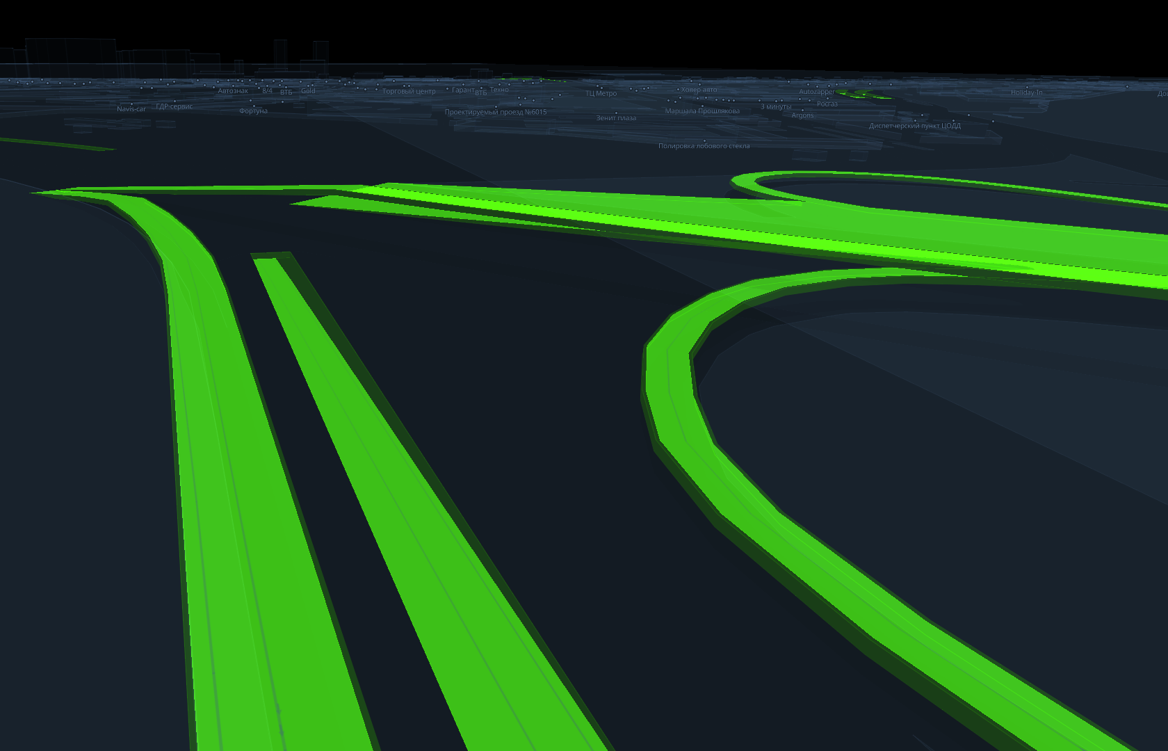
Immersive road infrastructure renders roads as realistic 3D objects instead of schematic lines. This increases map detail and improves the sense of presence, especially when combined with other immersive features such as 3D terrain, lighting, and 3D models.
Infrastructure components
Immersive road infrastructure includes the following objects:
-
Example of a data filter for the 3D model layer:
[
    "match",
    ["get", "db_sublayer"],
    ["Road_support_column"],
    true,
    false
] -
Example of a data filter for the Polygon layer:
[
    "match",
    ["get", "db_sublayer"],
    ["Transport_Roadbed"],
    true,
    false
] -
Example of a data filter for the Polygon layer:
[
    "==",
    ["get", "sublayer"],
    "PolygonMarkings_waffle"
] -
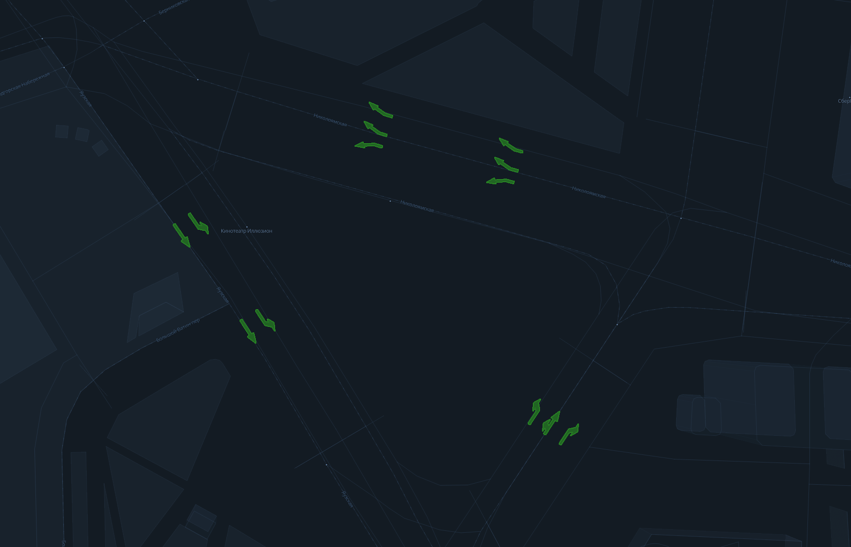
Example of a data filter for the Metric point layer:
[
    "==",
    ["get", "sublayer"],
    "PointMarkings_lane_directions"
] -

Example of a data filter for the Line layer:
[
    "==",
    ["get", "sublayer"],
    "LinearMarking_ParkingPlaces"
] -
Example of a data filter for the Overpass layer:
[
    "match",
    ["get", "sublayer"],
    [
        "Roadbed",
        "Main_Roadbed",
        "Gas_station_Roadbed",
        "Parking_Roadbed",
        "Constructed_Roadbed",
        "Intraquarter_Roadbed",
        "WithMarking_Roadbed",
        "Pocket_Roadbed",
        "PhysicalBarrier_Roadbed",
        "Road_bed_outline",
        "Roadbed_outline"
    ],
    true,
    false
]
Starting from a certain zoom level, these and other objects replace schematic linear roads. In base styles from the Style editor, the switch happens at zoom level 16.
Enabling immersive roads
Immersive data requires more resources (memory, CPU, and bandwidth) and may reduce device performance.
To display realistic road infrastructure on the map, use a prepared style and enable immersive mode through the API.
To enable the mode, set the global immersiveRoadsOn variable to true using the patchStyleState() method. After that, the map starts requesting tiles with immersive data. For more information on global variables, see the Global map style variables section.
map.patchStyleState({ immersiveRoadsOn: true });
To disable the mode, set the global immersiveRoadsOn variable to false. After that, tiles with immersive data are no longer requested.
map.patchStyleState({ immersiveRoadsOn: false });
Configuring style layers
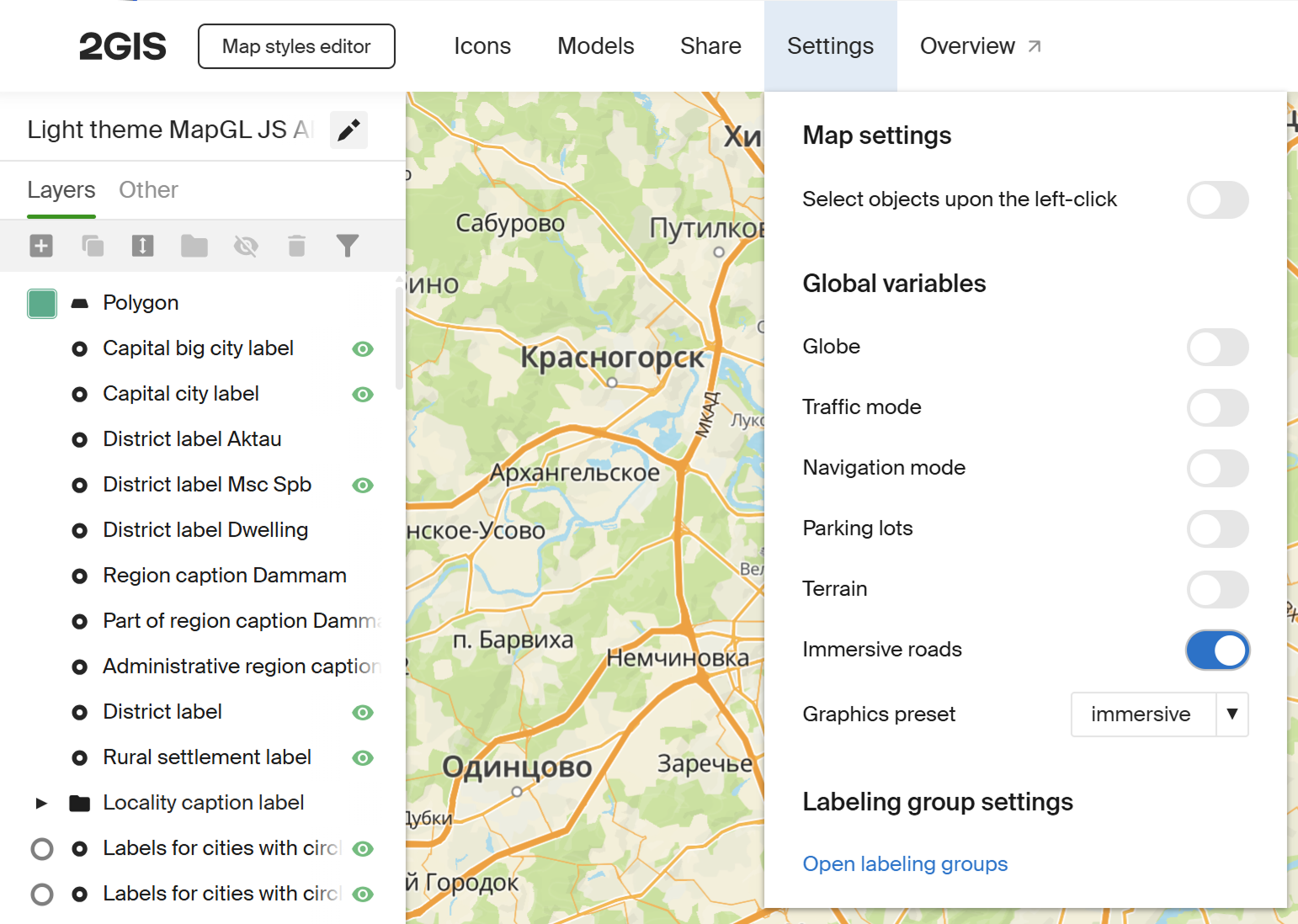
You can configure the displayed road infrastructure objects in the Style editor. To enable immersive mode in the Style Editor, turn on Immersive roads in the Settings section:
For more information about MapGL JS API layers, see the Style format specification and the Style editor documentation. To learn how to create a style based on a base style, see Creating styles and configuring style layers.
Among general settings, the display mode of non-immersive layers is important depending on whether an object has the db_has_immersive_counterpart attribute. This attribute indicates the presence of an immersive counterpart, an alternative immersive representation of the same road infrastructure object instead of the usual flat one.
For example, the Bike road layer in the base style uses the following value for the Layer display settings parameter on the Display tab:
[
    "match",
    ["get", "db_has_immersive_counterpart"],
    [1],
    false,
    true
]
This means:
- if an object has an immersive counterpart, the non-immersive layer is not rendered
- if there is no immersive counterpart, the object is rendered flat, ignoring levels
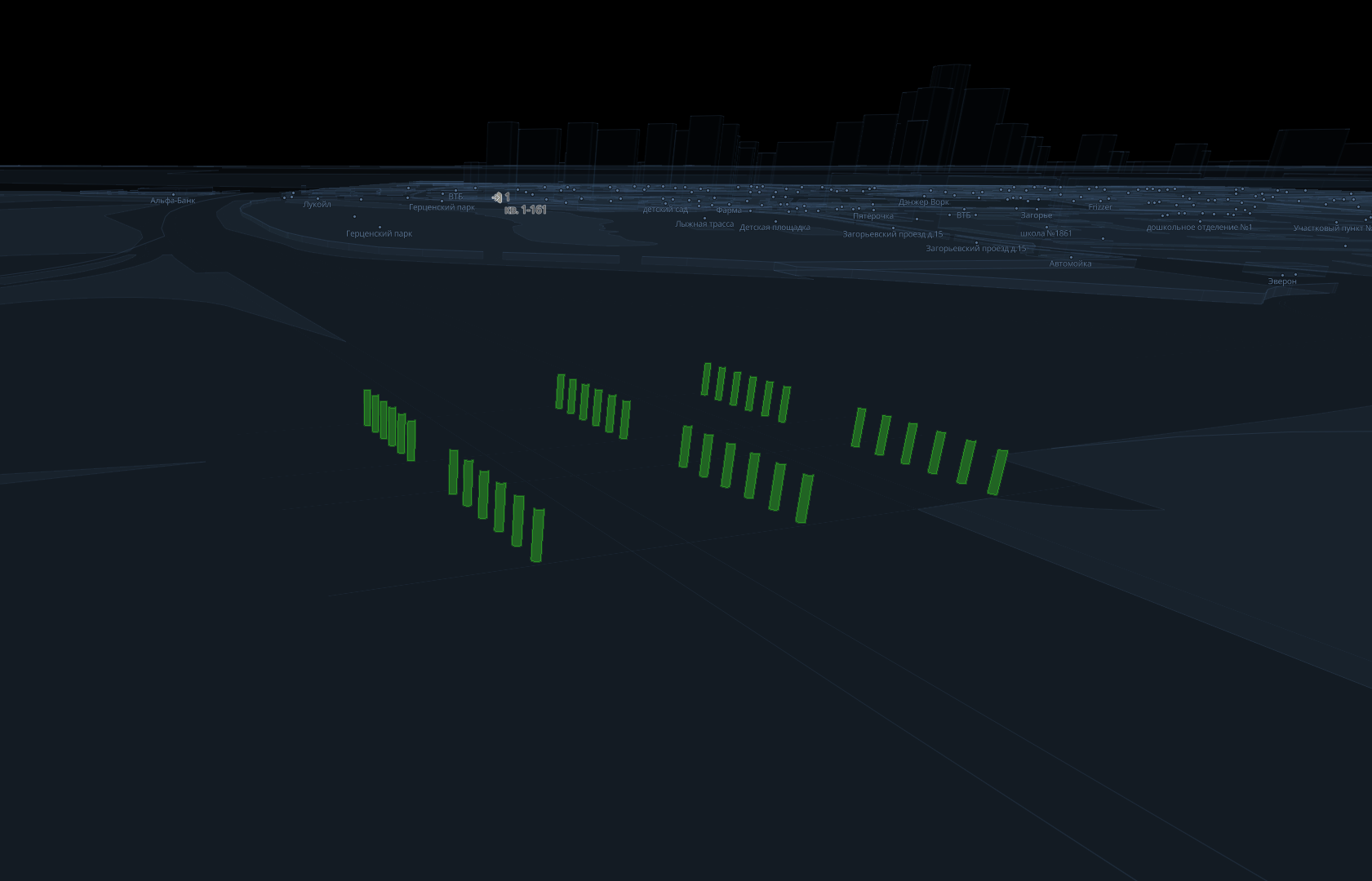
Pillars
In immersive mode, pillars for bridges and elevated roads are represented as 3D models in the glTF/GLB format.
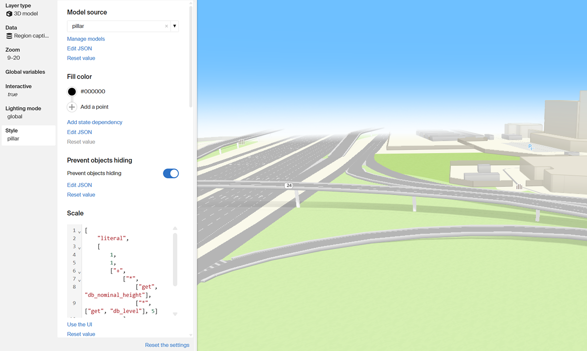
The Scale parameter for pillars is not a constant and is set with the following expression:
[
    "literal",
    [
        1,
        1,
        ["+",
            ["*",
                ["get", "db_nominal_height"],
                ["*", ["get", "db_level"], 5]
            ],
            -0.3
        ]
    ]
]
This expression aligns the pillar model with the interchange geometry: along the vertical axis, nominal height is multiplied by 5 (default span height) and by the current level, then 0.3 is subtracted so the pillars do not visually overlap with the interchange.
For more information on using 3D models on the map, see the 3D models section.
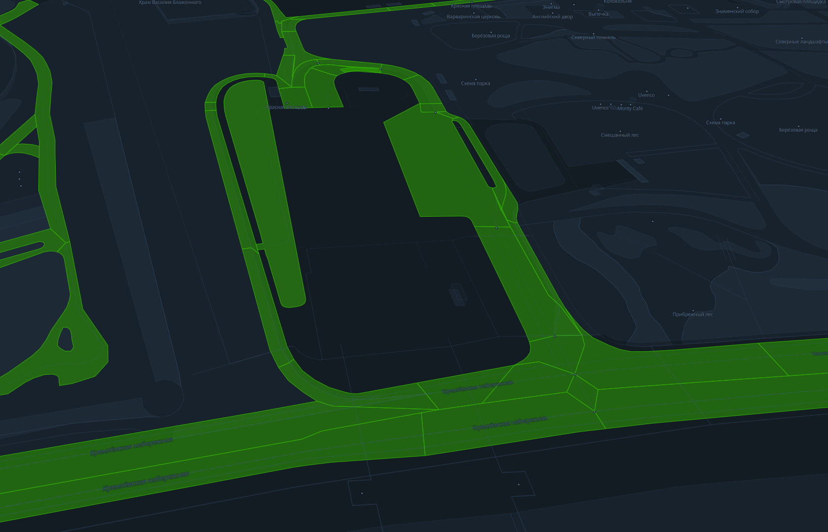
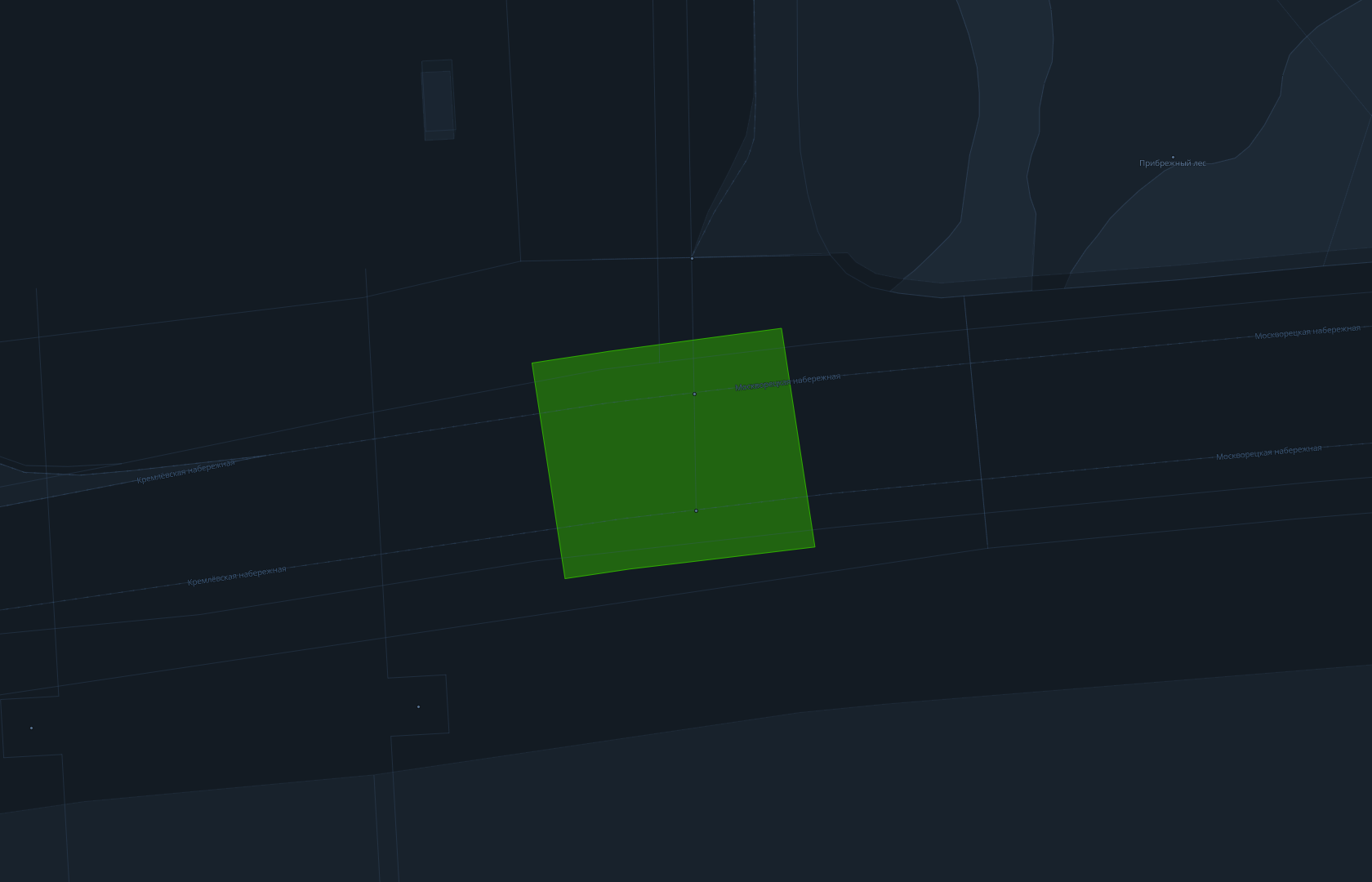
Roadbeds and area markings
Roadbeds and area markings (for example, box junctions) are rendered using the Polygon layer. For this layer, you can configure:
-
texture:
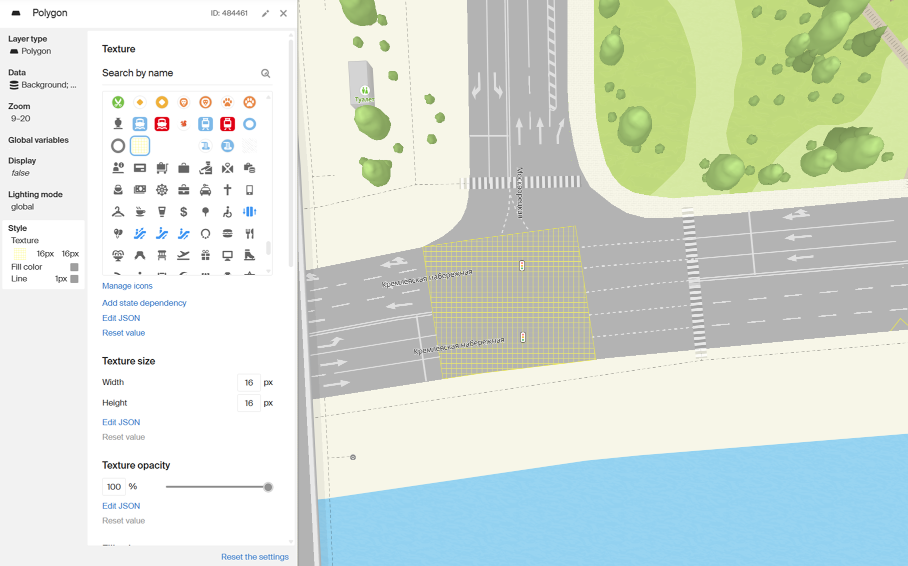
For more information, see Polygon texture fill.
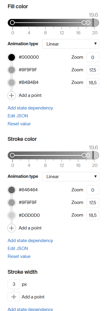
-
fill and stroke color:
Point markings
Point markings are displayed using the Metric point layer. This layer type is suitable for direction arrows, pedestrian crossings, and other point road marking elements.
To configure point markings in the Style editor, you can set:
- an icon
- icon fill color and opacity
- icon rotation
- icon size
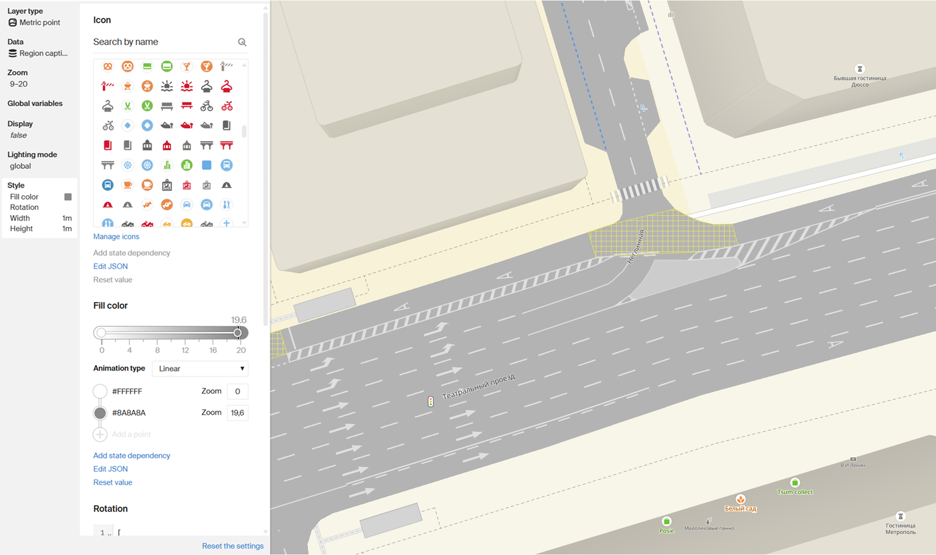
Rotation angle is set using a get expression, so it can be different for each object.
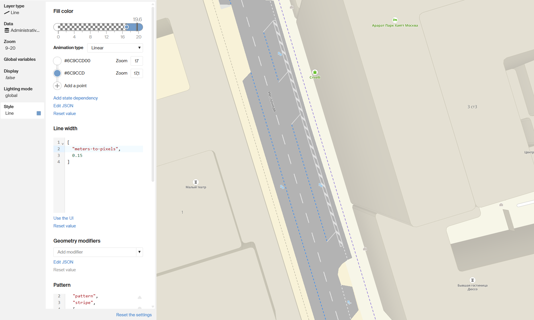
Linear markings
Linear markings are rendered using the Line layer. This layer type is used for lane dividers, edge lines, and other linear road marking elements.
To configure linear markings in the Style editor, you can set:
- fill color and opacity
- line width
- pattern type
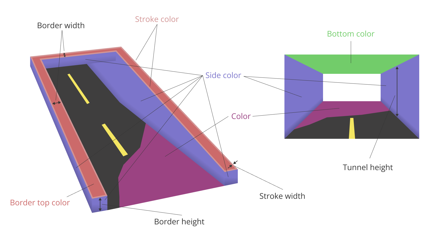
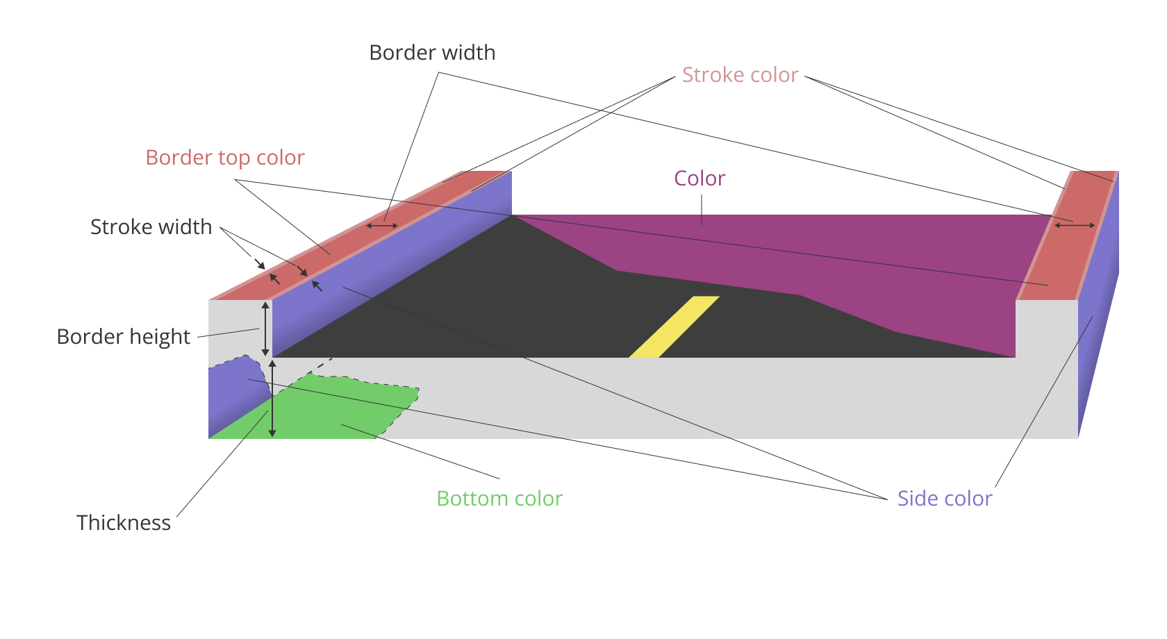
Interchanges and tunnels
Interchanges and tunnels are rendered on the map using the Overpass layer. You can edit this layer when working with a style template in the Style editor.
Interchanges and tunnels have common parameters, except for:
- Thickness - used only for interchanges
- Tunnel height - used only for tunnels
Interchange parameters diagram:
Tunnel parameters diagram: